
Overview
Hi everyone –
I’ve been playing around with some very simple hardware that makes for exceptionally good home IoT devices at very low prices… and without connection to a surveillance cloud.
It’s all trivially easy to do – but, the documentation online is truly awful, meaning it took me a few weeks to get everything worked out.
So, instead, I’m hosting a geeks hour to show you how to do it easily.
We’ll chat about two different automation hubs (both of which can run on a raspberry pi or on another machine in a docker container) and some exceptionally simple/inexpensive wifi remote sensor hardware (NodeMCU on ESP8266 microcontrollers, with some simple temperature and humidity sensors).
Andrew
Prerecs
To prepare for the workshop, please download the following items to your local machine:
- ESP8266 Serial Drivers from Silicon Labs
- ESP8266 Firmware (I’ve pre-compiled this for you and am hosting it… but if you want to build your own, it’s easy, and you can do so here, just be sure to include the needed modules including wifi, your sensor type, etc. Again, contact me if you want more info.)
- ESPlorer (requires java)
- NodeMCU PyFlasher (Mac and Windows availible, if you’re running linux, you can either build it from source or write me and I’ll get you going.)
- Software for your NodeMCU device (in this case, homebridge-mcuiot – download all the Lua files, or clone the whole repo)
Session Instructions
Preparing your hardware
- Your kit should come with four parts:
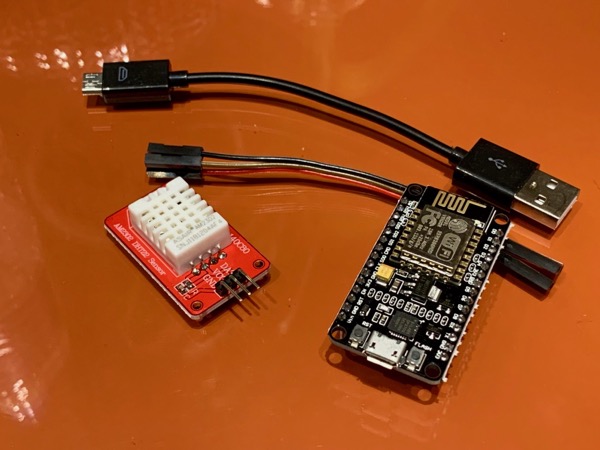
- NodeMCU Microcontroller
- AM2302 (DHT22) Temperature/Humidity Sensor
- Cables with pin adaptors
- Micro USB cable
- Putting software on the Microcontroller (please be sure you’ve already downloaded everything in the Prerecs section above)
- First, we’ll install the Silicon Labs drivers for your system
- Next, we’ll use the the NodeMCU PyFlasher to load the firmware onto the microcontroller
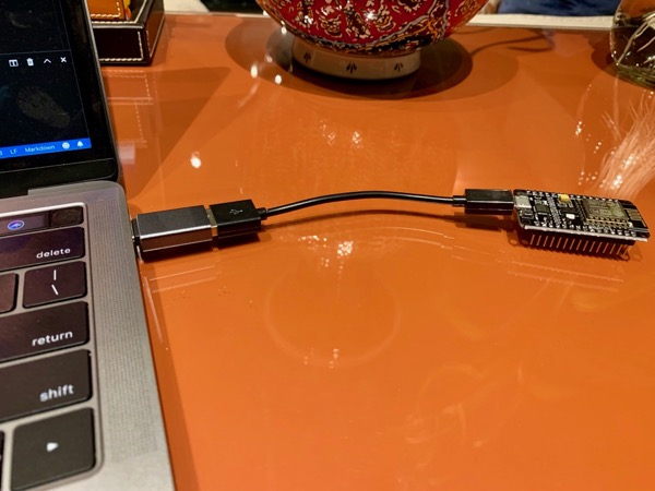
- Connect your microcontroler to your laptop with the included USB cable.
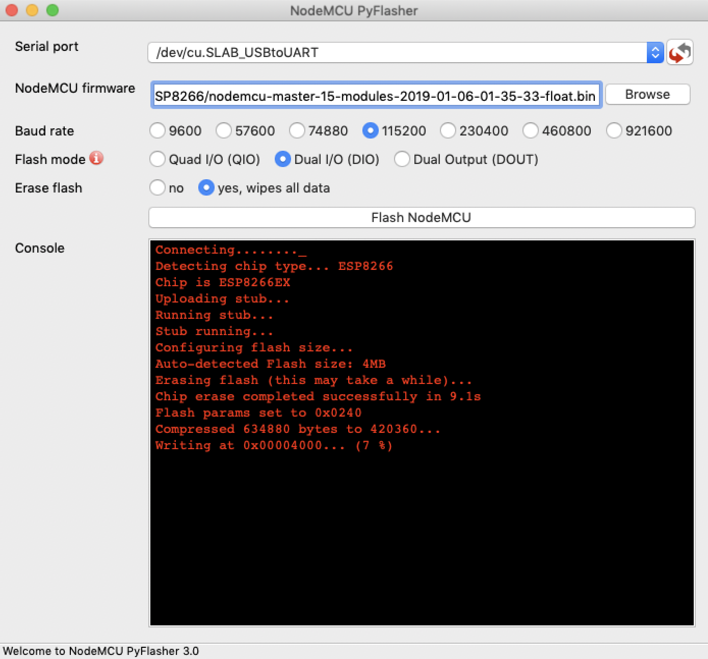
- Open PyFlasher, select the select the correct serial port from the list, and pick the correct connection speed and type. The ones in the screenshot seem to work well for these devices, but your milage may vary… Be sure to try things if they don’t work for you.
- Select the firmware to load, choose erase flash, and then click the big ‘Flash NodeMCU’ Button!
- Connect your microcontroler to your laptop with the included USB cable.
- Now that we have NodeMCU on your microcontroller, we need to install the software to read from the sensor and publish the data over HTTP. For this project, we’re using homebridge-mcuiot. We’ll use the ESPlorer to actually “install” the software on the microcontroller.
- After downloading all the files in the
luafolder, we need to edit a two of them.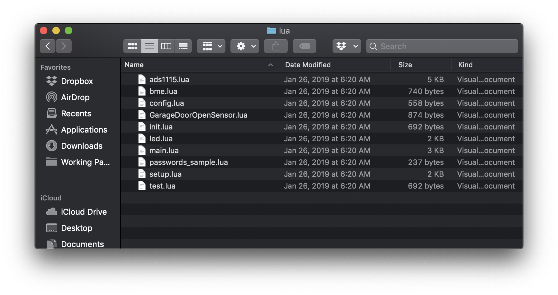
- First, we’ll add the correct WiFi information to the
passwords_sample.luafile. Note the file has blanks for two WiFi networks. Delete the second one. After you’re finished, rename the filepasswords.lua.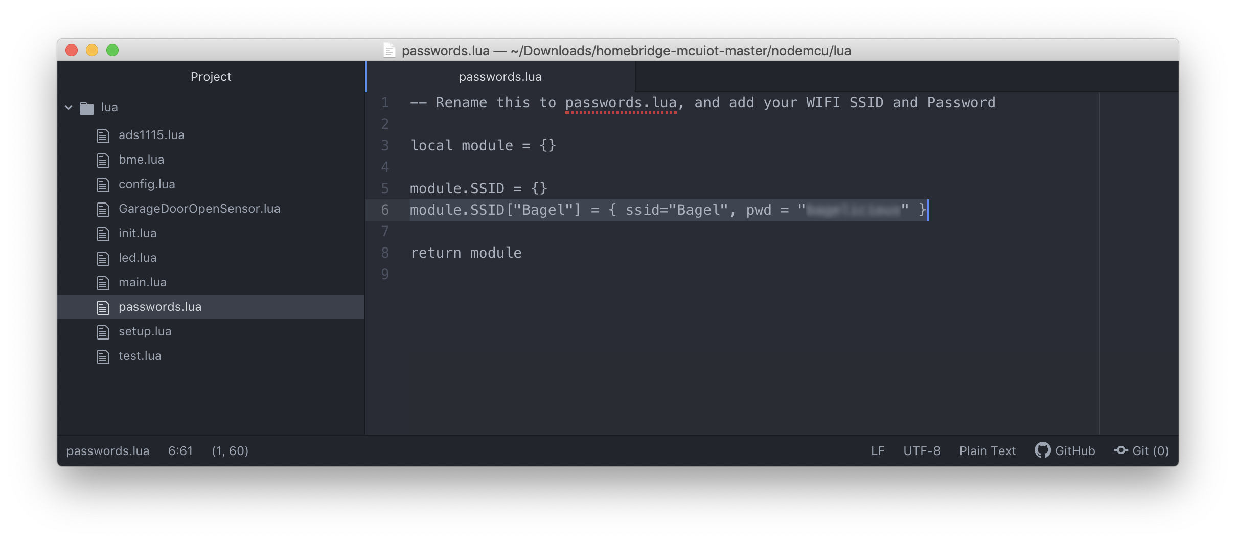
- Second, we need to edit the
config.luafile. Here we tell the microcontroller which type of sensor we’re using (line 4DHT), that we do not want the LEDs running all the time (line 82), and which pin we will use for data from the sensor (line 175– we’ll use pin 5, because it’s next to the ground and power pins).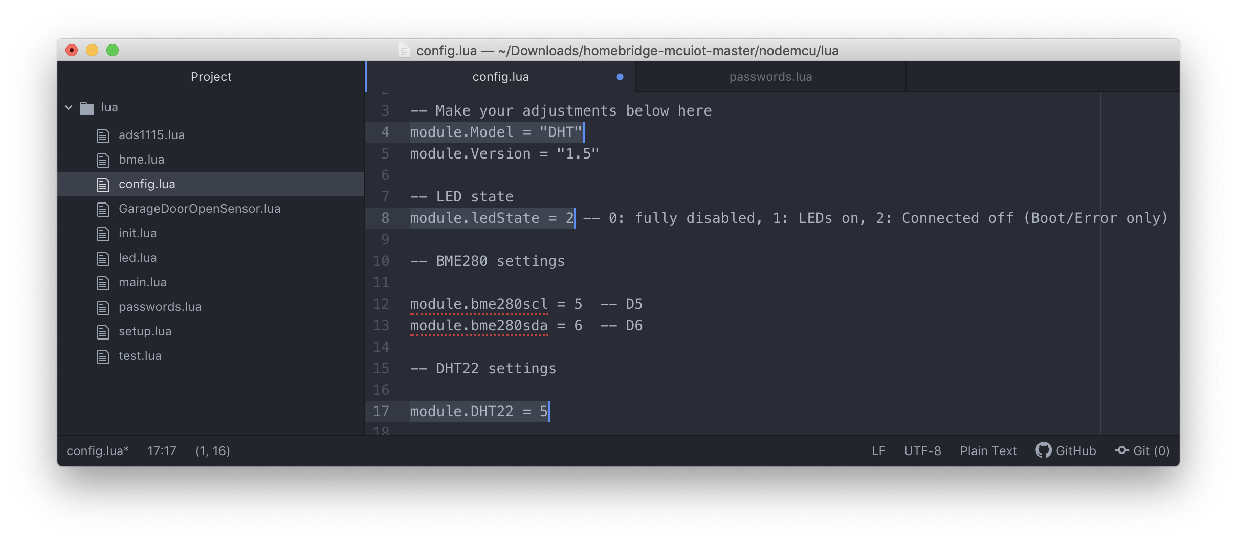
- First, we’ll add the correct WiFi information to the
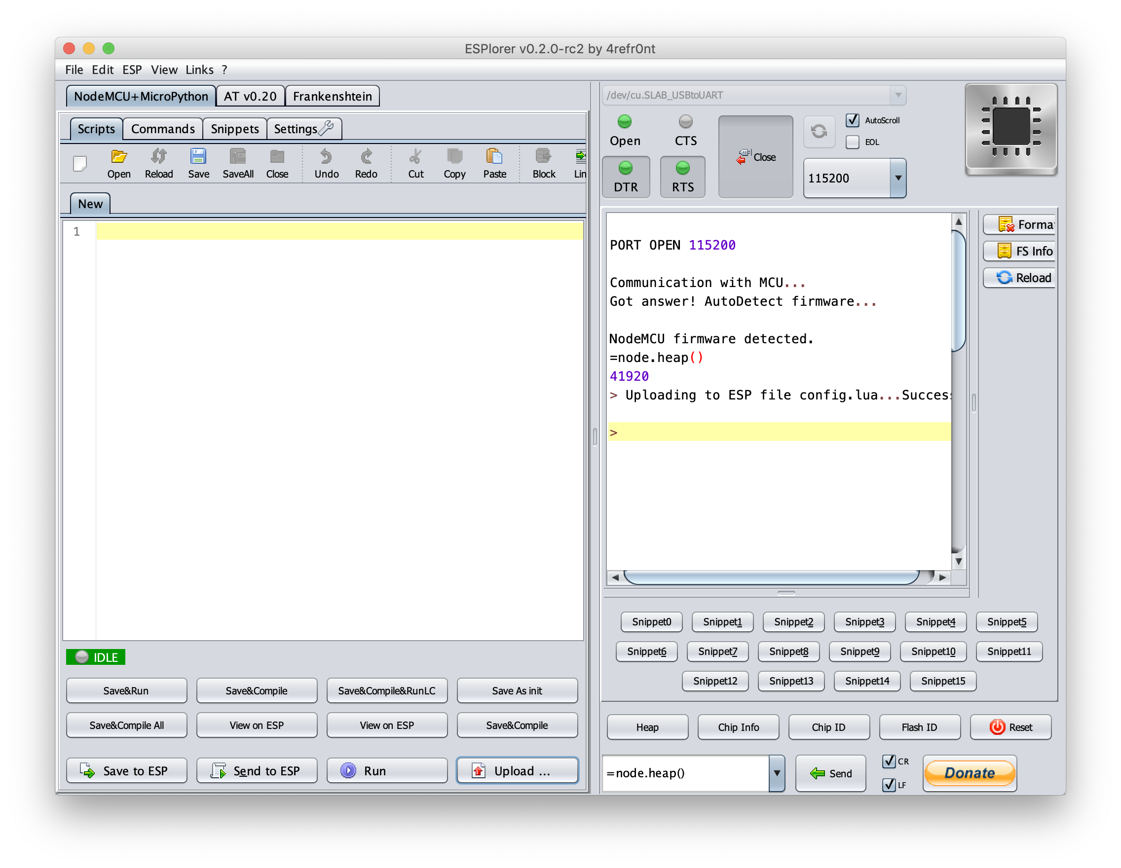
- Now, we need to connect to our functioning microcontroller using ESPlorer. To do so, we open the app, select the correct serial port, enable
DTRandRTSand set the bitrate to115200. Then we click the bigopenbutton.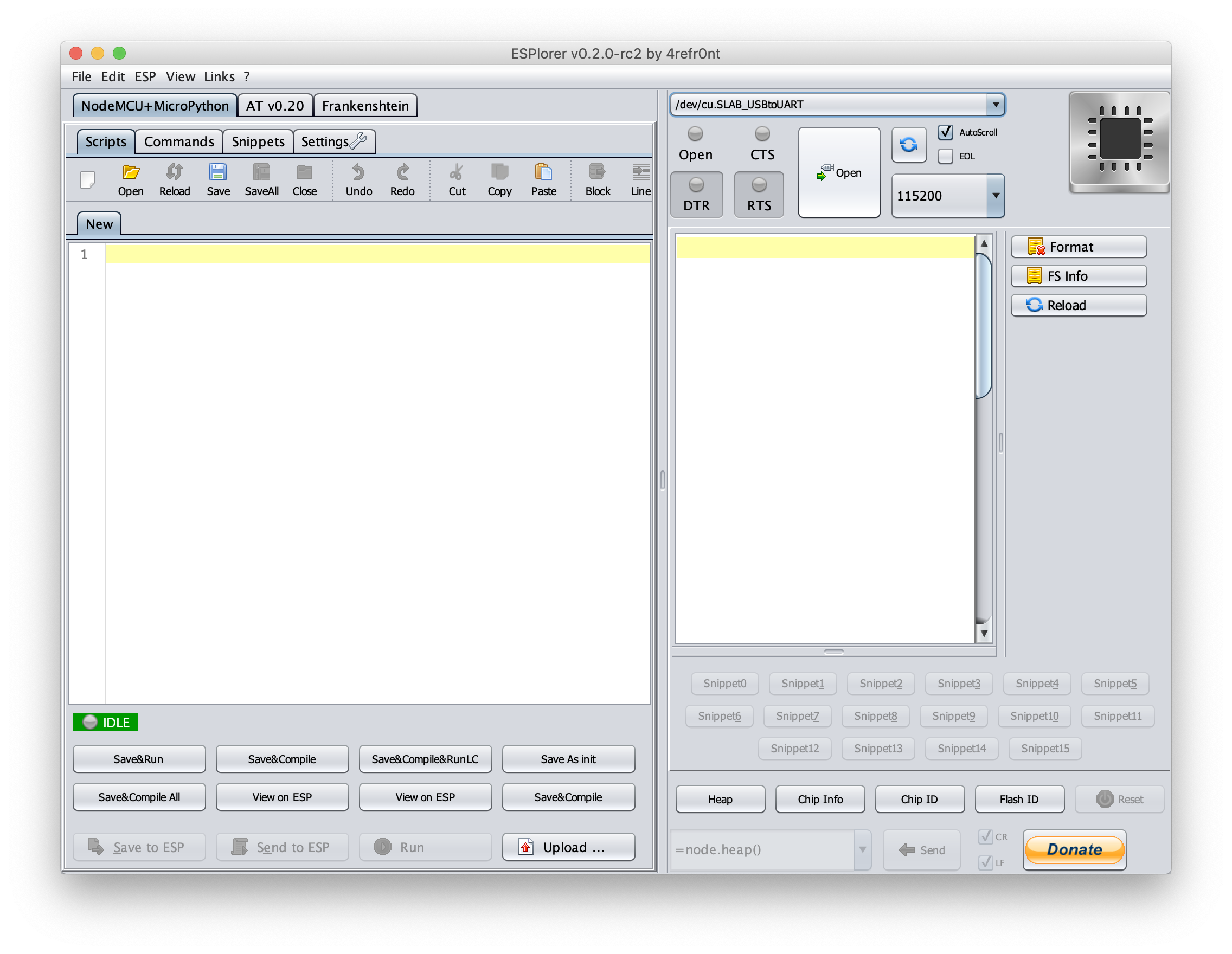
- Once connected, we can upload the
homebridge-mcuiotsoftware. To do so, we must upload six files individually, by clicking the upload button, finding them on our system, and clicking open for each. The five files we need to upload are:- config.lua
- led.lua
- main.lua
- passwords.lua
- setup.lua
- test.lua
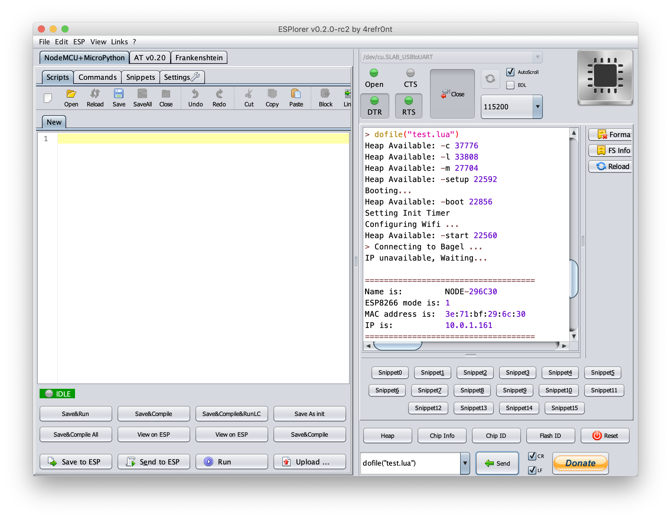
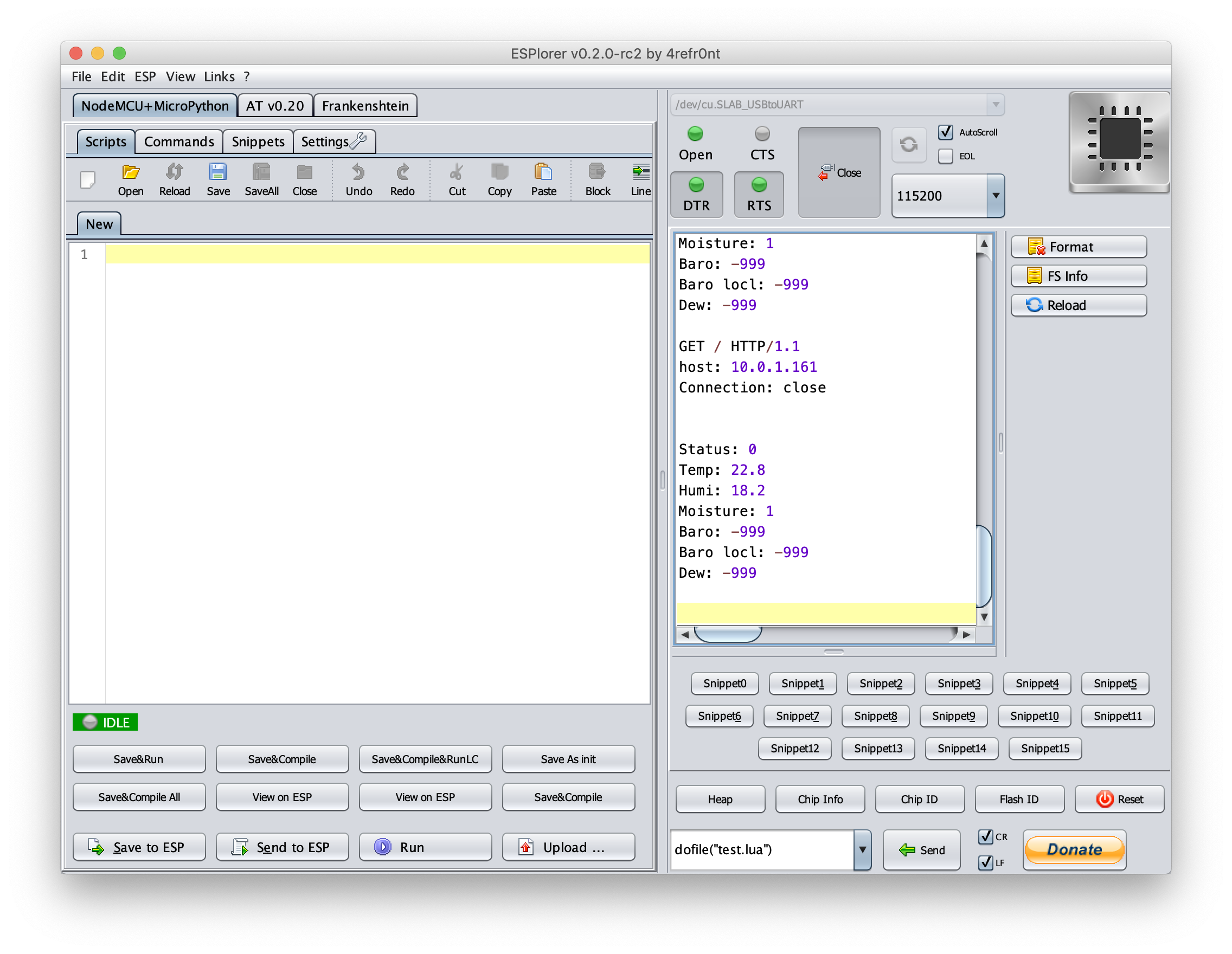
- After uploading all the files, we can now test our microcontroller to see if it can connect to WiFi. We use the ESplorer to run the test by selecting
dofile("")from the action menu; editing it to add our test tool, so it readsdofile("test.lua"), and then clicking the send button. If the microcontroller panics, it will reboot. Run the test file again. (This happens with regularity.)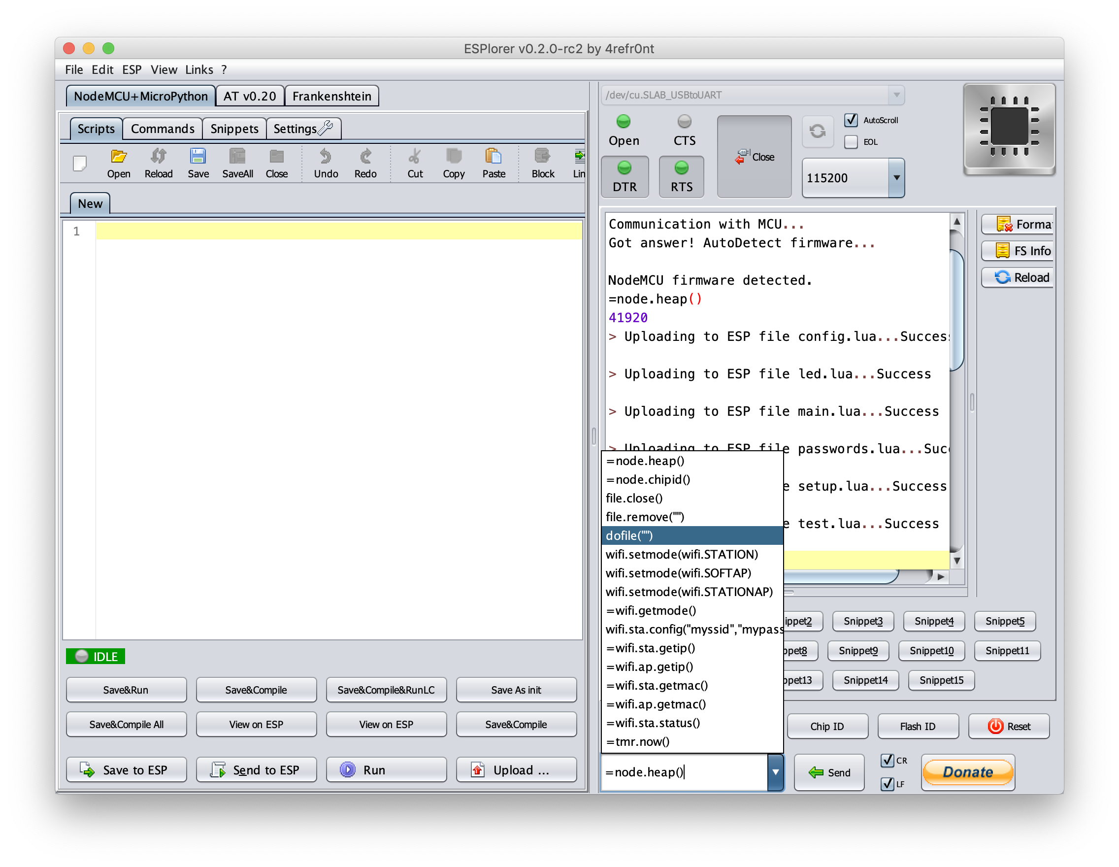 If the test is successful, ESPlorer will display the connected WiFi network and the device’s IP address.
- After downloading all the files in the
- Next, we’ll attach our sensor to the microcontroller.
- Close ESplorer and unplug your microcontroller from your laptop.
- Attach your pin cables to the
3V3,GND, andD5pins. They’re all next to one another.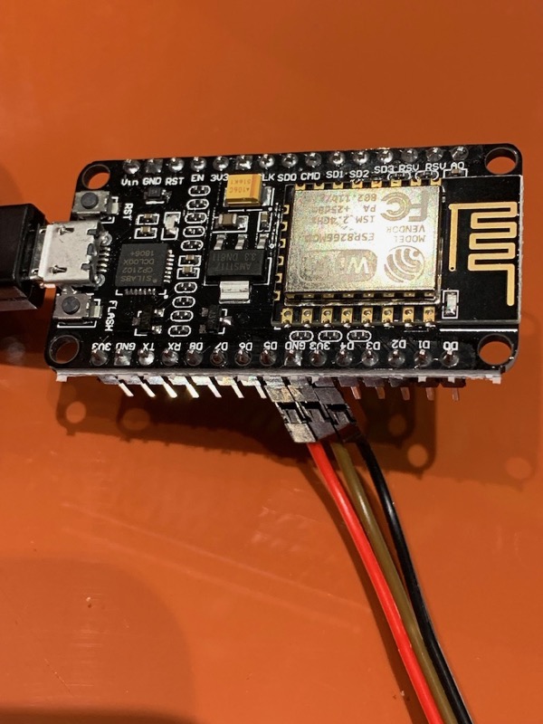
- Using the colors of your pin cables as your guide, make the following connections on your AM2302 sensor module:
3V3–>VCC(middle pin)GND–>GND(bottom pin)D5–>DAT(top pin)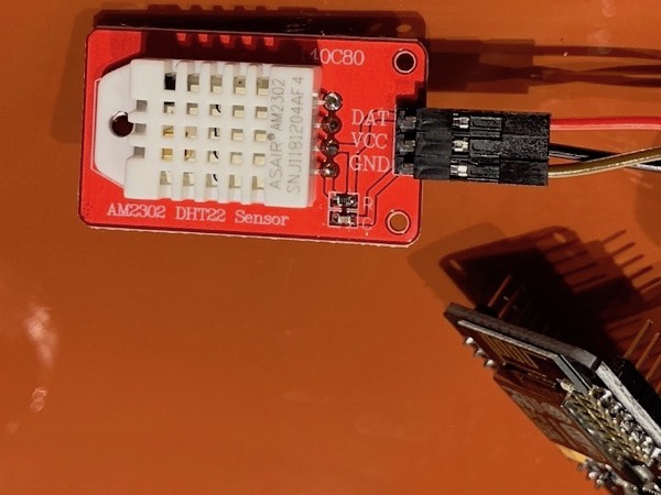
- Now we can re-connect the microcontroller to your laptop via USB, and see if it is pulling data from the sensor.
- After re-connecting, open ESPlorer and open the connection again (it should have saved your settings from before).
- Run the test file again, by entering
dofile("test.lua")into the action menu and clicking send. - If you connected the sensor correctly, ESPlorer will show you the readout from the sensor, as illustrated below.
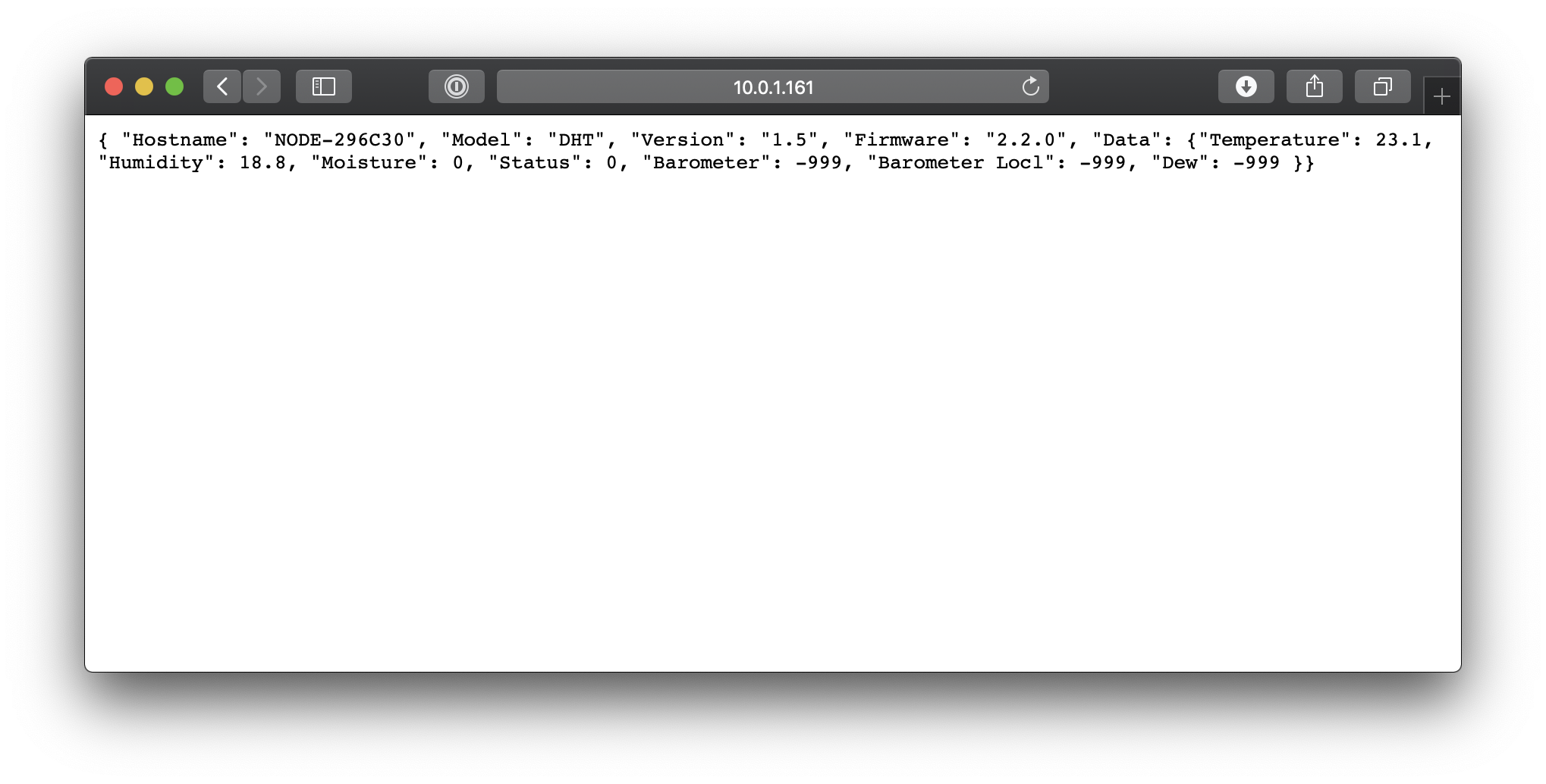
- To access the data remotely, you can visit the IP address shown by ESPlorer in your browser. It’s a simple JSON formatted file, accessible by HTTP. You can incorporate this into your own application, or use many different home automation tools to read this file. If you use the Apple ecosystem, you can install the client portion of homebridge-mcuiot along with homebridge. There is good documentation for this on the sites for both pieces of software.
- Once you’re ready to perminently install your sensor, we need to add one more file to our microcontroller,
init.lua, which tells it to run the homebridge-mcuiot software on boot. To do so, click the upload button, find theinit.luafile downloaded earlier, and click open. - Congrats! Go plug your controller in somewhere!